-
摘要: 本文综述了炭材料用于水脱盐的电容去离子化(CDI)电极的研究进展。首先,基于盐吸附容量(SAC)、吸附速率(SAR)和电荷效率(CE)比较了各种类型的CDI反应池,包括流动型(FB)、膜型(M)、流经电极型(FTE)以及流动电极(FE)型反应池。进而,基于电容和电池两种类型重点讨论了炭电极材料的研究进展。研究表明,具有短路运行模式的流动电极(FE)反应池可望用于实际应用以解决未来日益增长的缺水需求。Abstract: Recent developments on the capacitive deionization (CDI) technique for water desalination are reviewed with a focus on carbon as the electrode material. The capacity and rate of salt adsorption and charge efficiency of various types of CDI cells, i.e. flow-by, membrane, flow-through-electrode, and flowing electrode cells are compared. Various carbon electrode materials for capacitor-type and battery-type cells are discussed. The flowing electrode cell with the short-circuit operation mode seems to be the most promising one for practical applications.
-
Key words:
- Carbon materials /
- Capacitive deionization /
- Water desalination /
- Capacitor-type /
- Battery-type
-

Figure 2. SEM images of the carbons prepared from the powder mixture of potassium citrate (P), urea (U) and ammonium citrate (A) by carbonization at 800 °C. (a, e) PCP, (b, f) PCPA, (c, g) PCPU, and (d, h) PCPUA. Reprinted with permission from Ref.[11]. Copyright (2023) by Elsevier

Figure 3. CDI performance of the hierarchically porous carbons prepared from potassium citrate, urea and ammonium citrate by carbonization at 800 °C: the changes of SAC with (a) time, (b) applied voltage and (c) initial NaCl concentration. Reprinted with permission from Ref.[11]. Copyright (2023) by Elsevier

Figure 4. CDI performance of the basswood-derived carbon thin section in comparison with an AC: (a) conductivity change during the first desalination/regeneration cycle, (b) conductivity and (c) SAC change with cycle. Reprinted with permission from Ref. [12]. Copyright (2018) by American Chemical Society

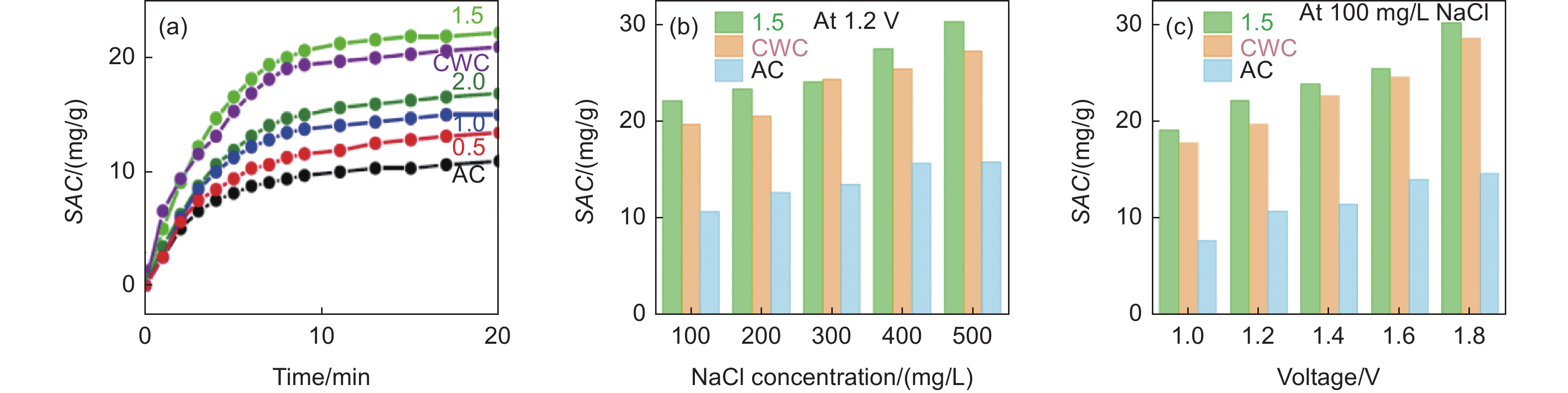
Figure 5. CDI performance of the carbons derived from cocoon wastewater (CW) using different ZnCl2 concentrations (0.0-2.0 mol/L) in CW aqueous solutions in comparison with a commercial activated carbon (AC): (a) SAC changes with time for the carbons prepared by using different ZnCl2 concentrations in comparison with AC, (b) effects of the NaCl initial concentration and (c) applied voltage on SAC for the carbons CWC-1.5 and CWC-0.0. Reprinted with permission from Ref. [13]. Copyright (2023) by Elsevier

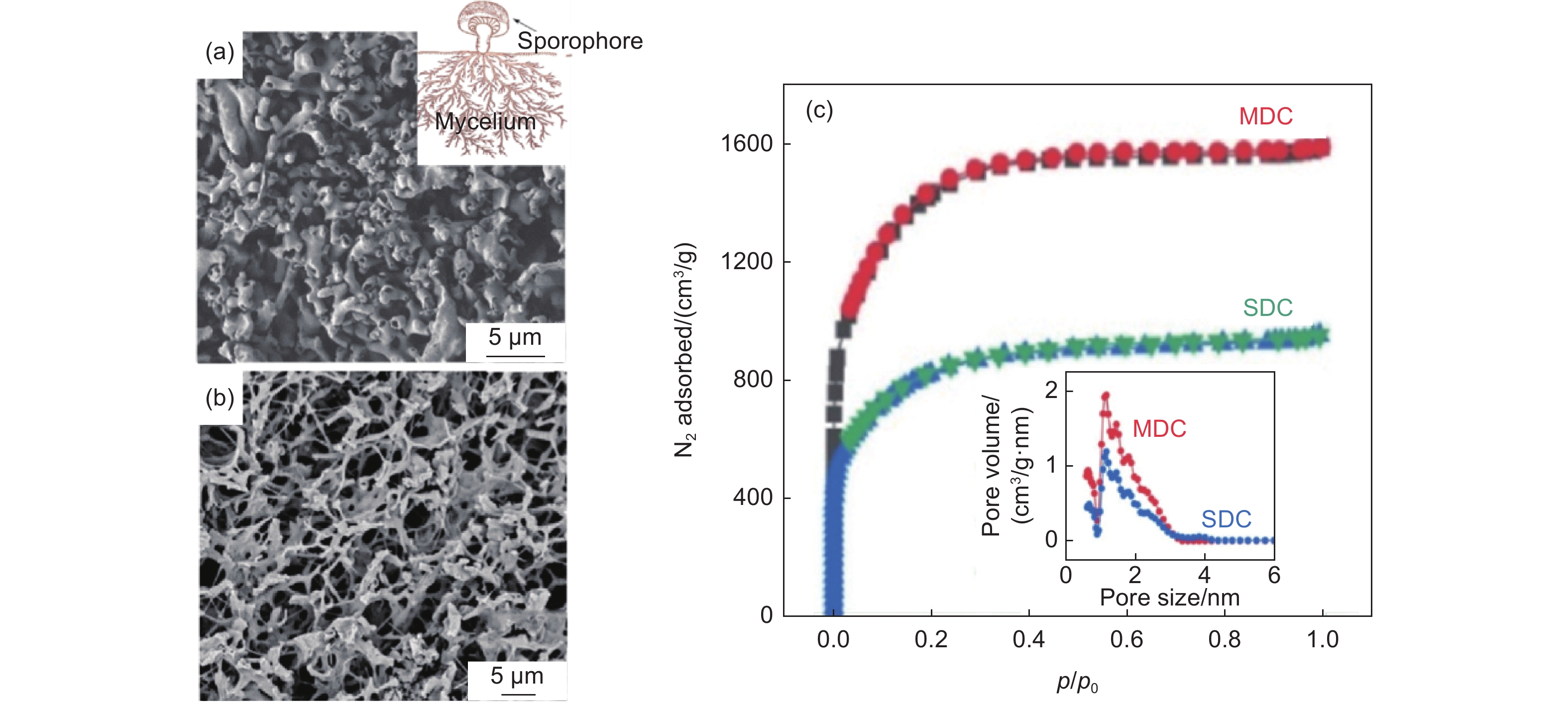
Figure 6. Carbon derived from mushroom mycelium using ZnCl2 template carbonization/KOH-activation at 800 °C (MDC): (a) SEM image of the pristine mycelium with illustration, (b) that of the carbon after activation, and (c) N2 adsorption-desorption isotherms at 77 K with the pore-size distribution for MDC and SDC (inset). Reprinted with permission from Ref. [14]. Copyright (2022) by Elsevier

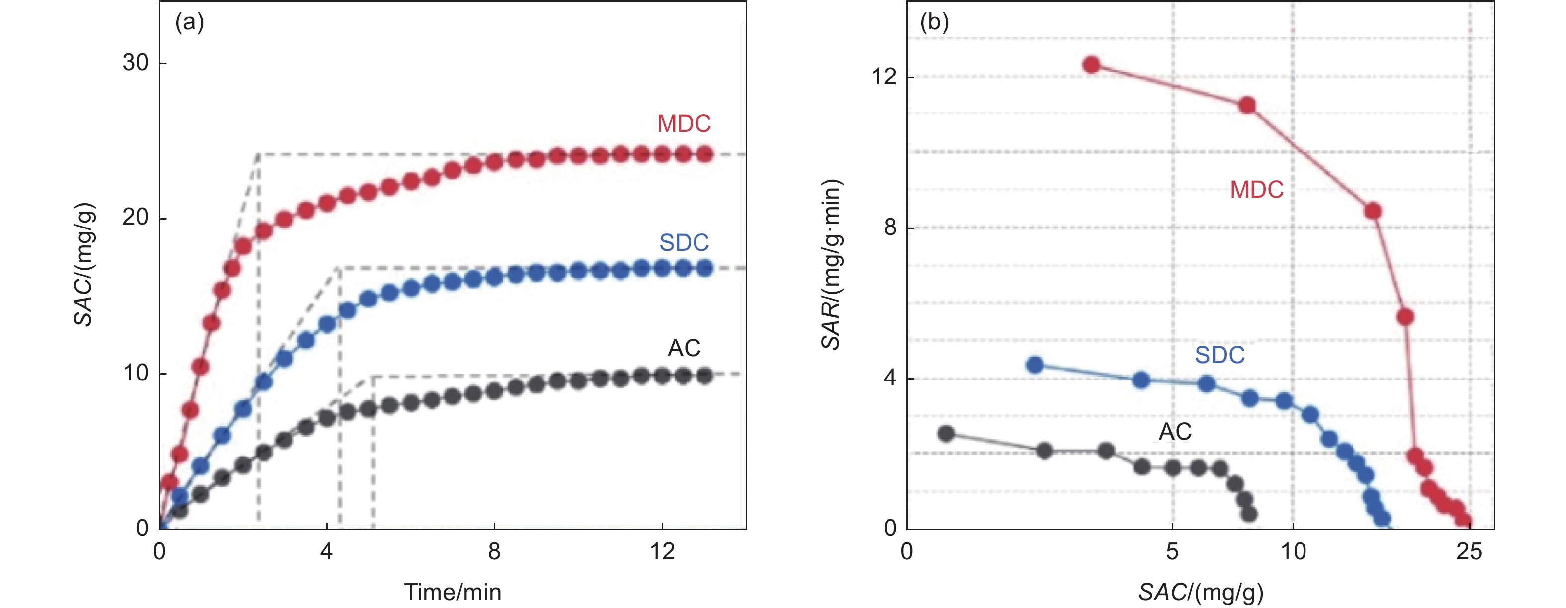
Figure 7. CDI performances of the carbons derived from mushroom mycelium (MDC) and sporophores (SDC) in a symmetric FB CDI cell in comparison with a commercial activated carbon (AC): (a) changes in SAC with time at the applied voltage of 1.4 V and the initial NaCl concentration of 500 mg/L, and (b) CDI Ragone plots. Reprinted with permission from Ref. [14]. Copyright (2022) by Elsevier

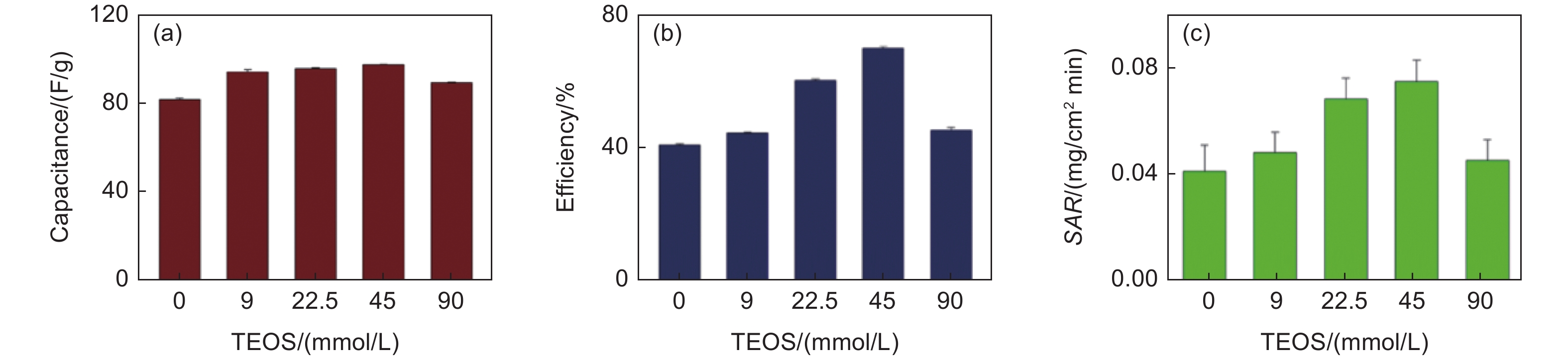
Figure 8. SiO2-nanoparticle-grafted ACCs: TEOS-concentration dependence of (a) capacitance of a three-electrode cell with 0.5 mol/L NaCl aqueous electrolyte, (b) desalination efficiency and (c) SAR measured in a symmetric FB-cell with 2.0×10⁻⁴ NaCl solution. Reprinted with permission from Ref. [20]. Copyright (2022) by Elsevier

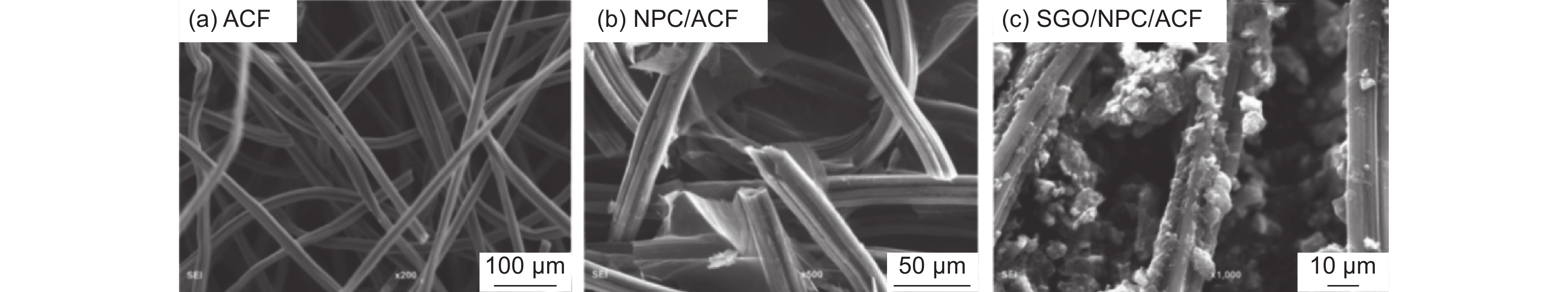
Figure 9. SEM images of the composites of the ACF with N-doped porous carbon (NPC) and single-layered GnO nanoflakes: (a) the pristine ACF, (b) the composite NPC/ACF and (c) single-layered-GnO/NPC/ACF composites. Reprinted with permission from Ref.[26]. Copyright (2022) by Elsevier

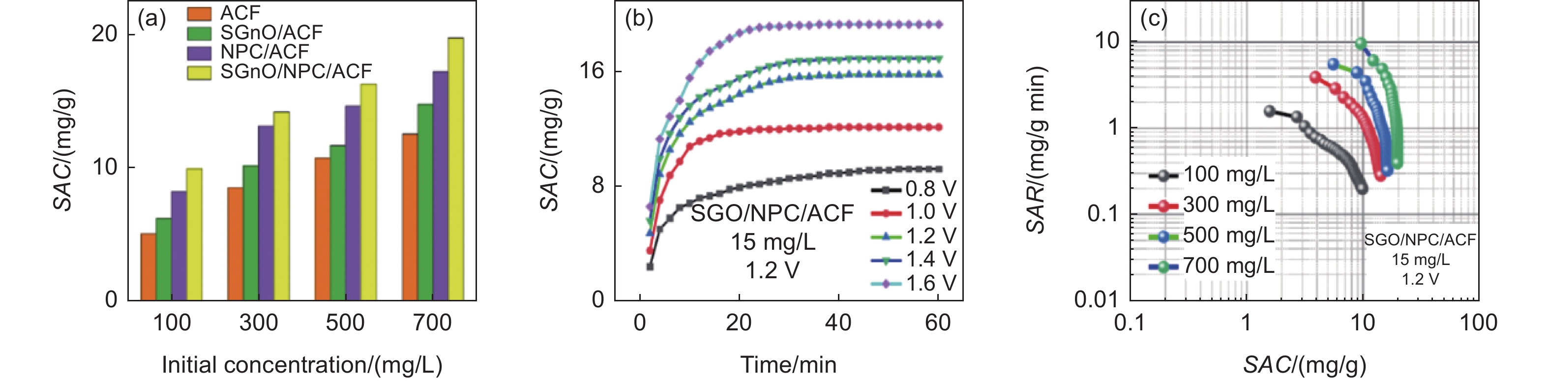
Figure 10. CDI performance of the composites of the activated carbon fibers (ACF) with N-doped porous carbon (NPC) and single-layered GnO nanoflakes: (a) SAC as a function of initial NaCl concentration on 4 composites, (b) change of SAC with time and (c) CDI Ragone plot for the composite single-layered-GnO/NPC/ACF. Reprinted with permission from Ref.[26]. Copyright (2022) by Elsevier

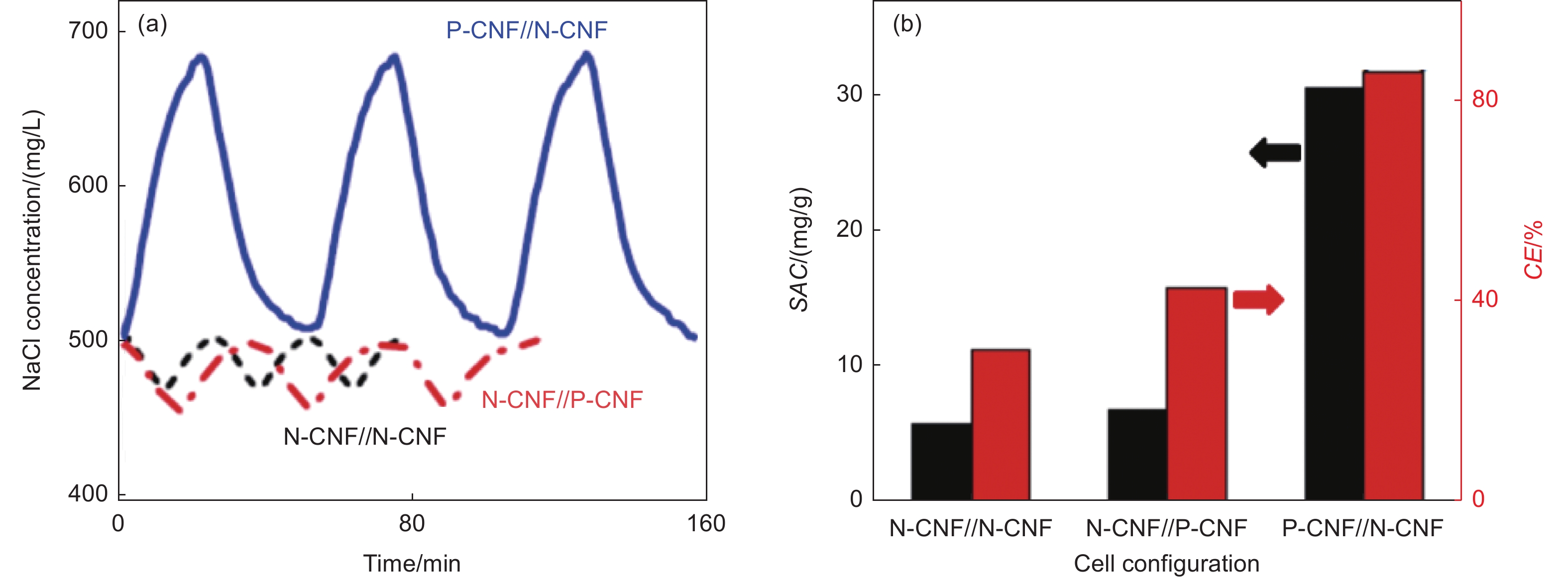
Figure 11. Desalination performance of CDI cells using PAN-based carbon nanofibers (CNFs), symmetric FB-cell, N-CNF//P-CNF and asymmetric FB-cell, P-CNF//N-CNF as the electrode materials: (a) kinetics of NaCl concentration changes and (b) comparison of SAC and CE for three cells. Reprinted with permission from Ref.[27]. Copyright (2021) by Elsevier

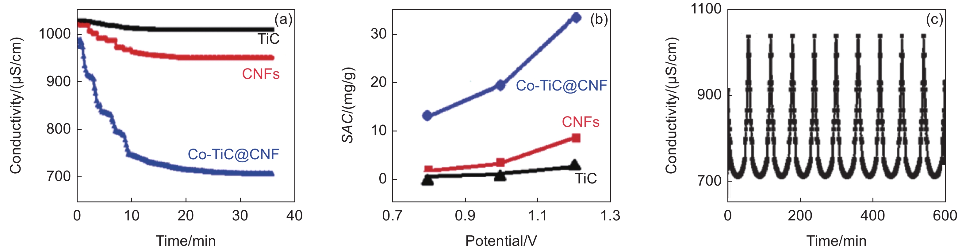
Figure 12. CDI performance in a flow of NaCl solution with 15 mL/min rate for the composite Co-TiC@CNF, the pristine CNFs and TiC: (a) changes in conductivity of NaCl effluents, (b) dependences of SAC on the applied potential and (c) desalination-regeneration cycling of the composite at 1.2 V. Reprinted with permission from Ref.[28]. Copyright (2022) by Elsevier

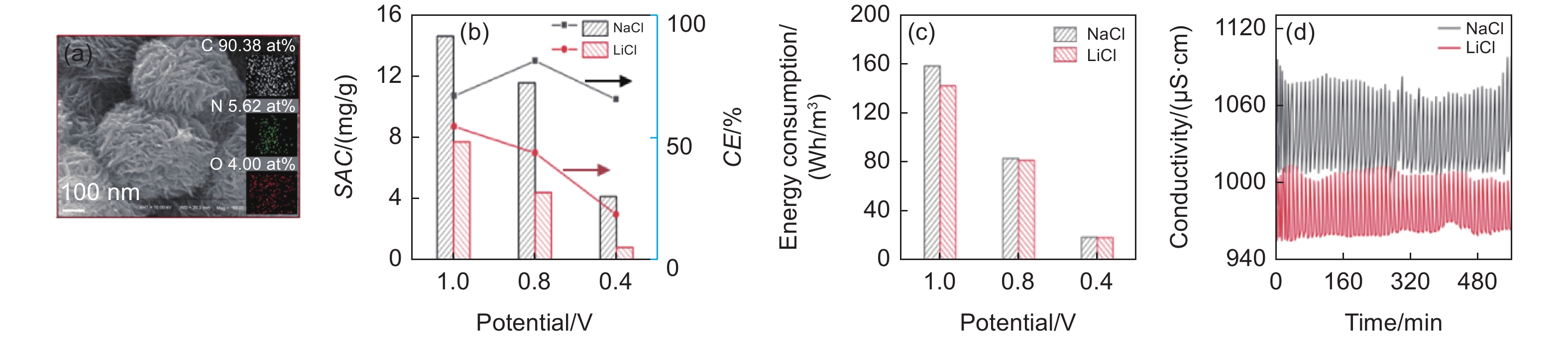
Figure 13. CDI performance of N-doped carbon microspheres with vertically aligned carbon nanosheets prepared from a polyimide by carbonization at 800 °C and activated with KOH for NaCl and LiCl aqueous solutions: (a) SEM image, (b) changes in SAC and CE with potential applied, (c) changes in energy consumption with potential applied, and (d) conductivity change with cycling up to 56 cycles. Reprinted with permission from Ref.[29]. Copyright (2021) by Elsevier

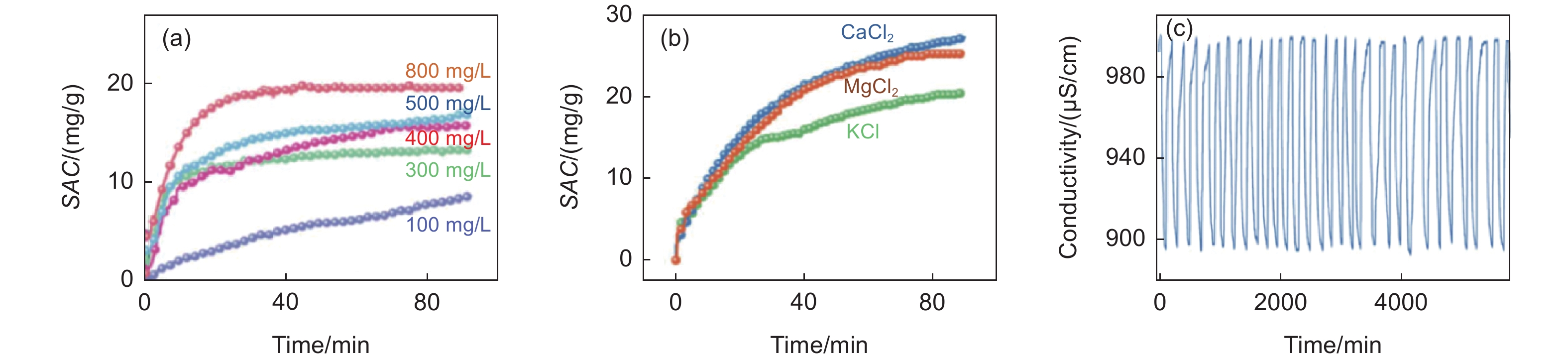
Figure 14. CDI performance of the composite CNFZIF: (a) SAC for NaCl solutions with different concentrations (100-800 mg/L, (b) SACs for 5 mmol/L KCl, CaCl2 and MgCl2 solutions, and (c) cycle performance for 500 mg/L NaCl solution at 1.2 V[30]

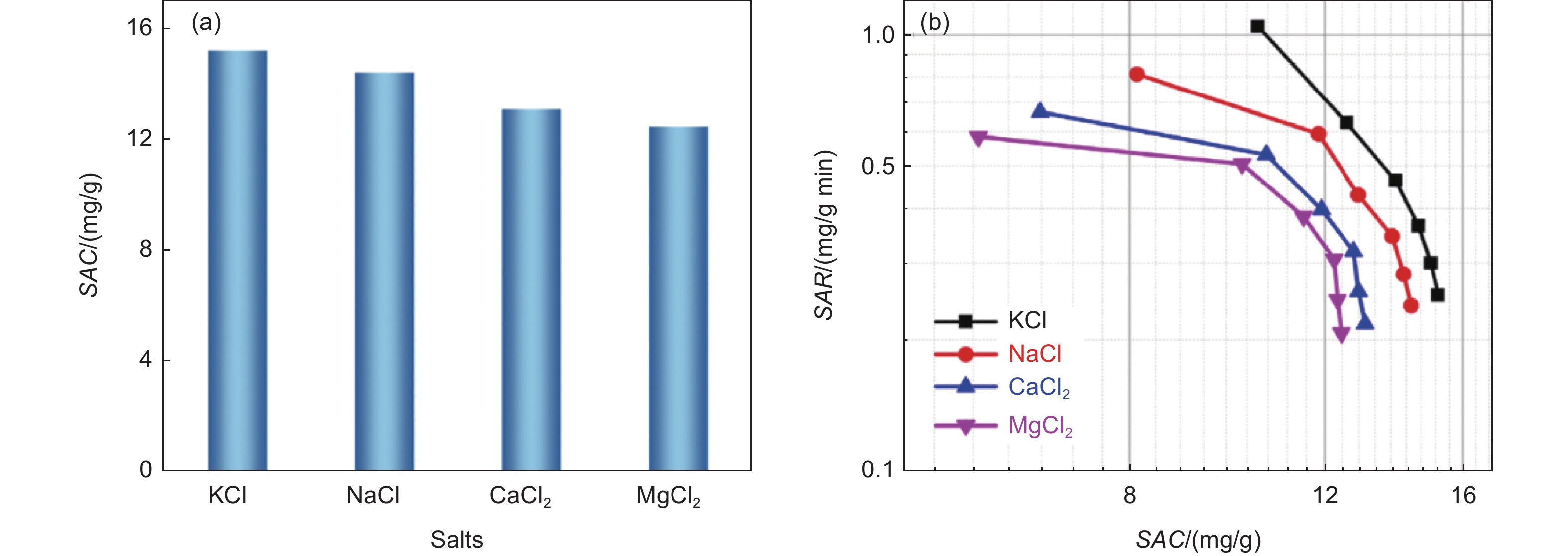
Figure 15. CDI performances of the free-standing N-doped rGtO foam prepared using polystyrene spheres template for different salts: (a) SAC and (b) Ragone plot. Reprinted with permission from Ref.[32]. Copyright (2022) by Elsevier

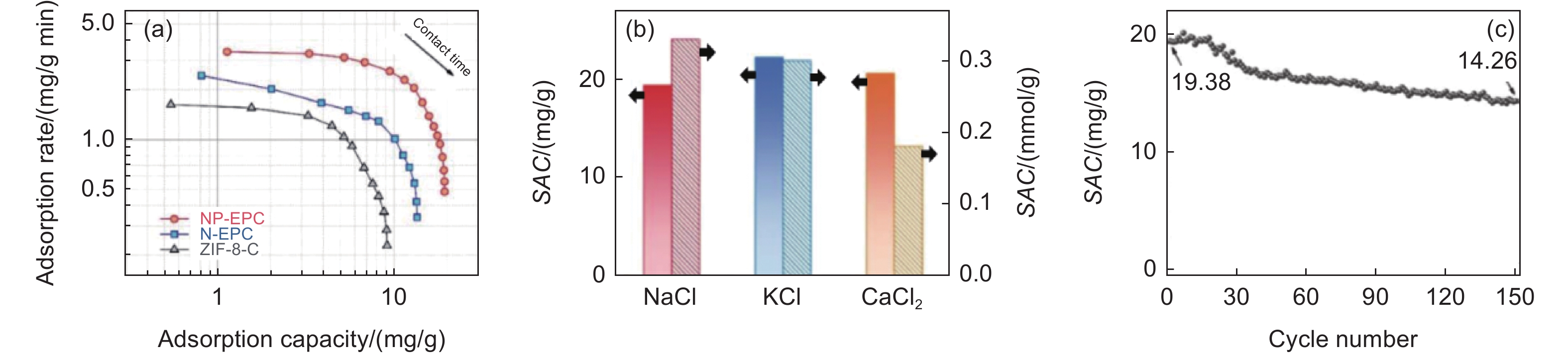
Figure 16. Performances of symmetric FB-CDI cells using electrodes of the carbons derived from ZIF-8, ZIF-8-C, N-EPC and NP-EPC: (a) CDI Ragone plots in NaCl solution, (b) adsorption capacities and rates of NP-EPC for different salts, and (c) cycle performance of NP-EPC in 500 mg/L NaCl solution at 1.2 V[33]

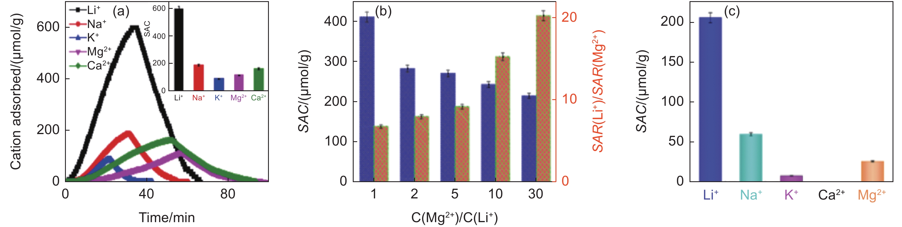
Figure 17. CDI performances of λ-MnO2/rGtO composite prepared using 0.2 g rGtO for different salts: (a) cations adsorbed with time from 10 mmol/L single-salt solutions with SAC for different cations (inset), and (b) dependences of SAC for Li+ and of the ratio of adsorption ratio (adsorption efficiency) SAR for Li+ to that for Mg2+ against concentration ratio of Mg2+ to Li+ in a mixed solution and (c) SACs measured in a synthetic salt lake brine. Reprinted with permission from Ref. [22]. Copyright (2022) by Elsevier

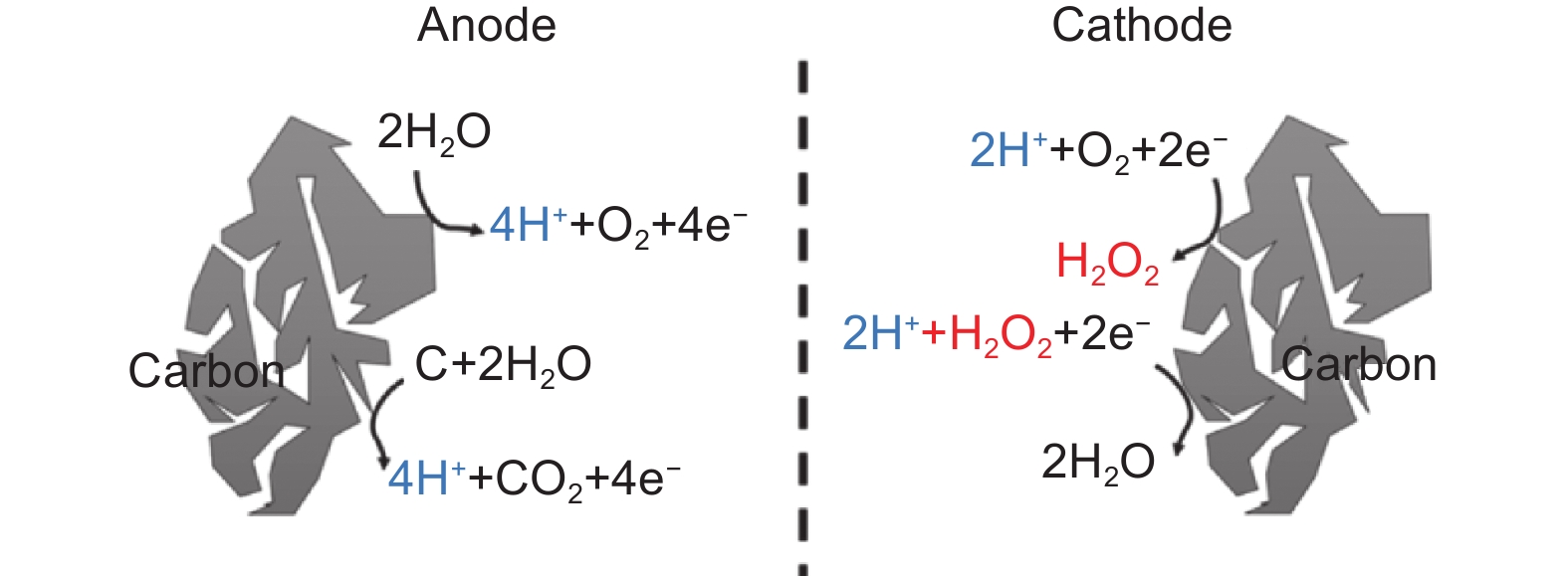
Figure 18. Faradaic reactions at the carbon electrodes during water desalination. Reprinted with permission from Ref.[38]. Copyright (2016) by American Chemical Society

Figure 19. CDI performance of N-doped carbons derived from EDTA by carbonization at 700, 750 and 800 °C in comparison with a commercial AC: dependences of SAC on the voltage applied in a flow of 5 mmol/L NaCl solution (a) in a de-aerated condition and (b) in an aerated condition, and cycle performance in an aerated condition. Reprinted with permission from Ref.[39]. Copyright (2021) by Elsevier

Figure 20. CDI performance of the MnO2/carbon composites: (a) adsorption-desorption kinetics in 100 mg/L NaCl solution by applying the potential of 1.2 and 0 V and (b) CV curve on the MnO2/AB composite obtained through indirect process. Reprinted with permission from Ref.[40]. Copyright (2020) by Elsevier

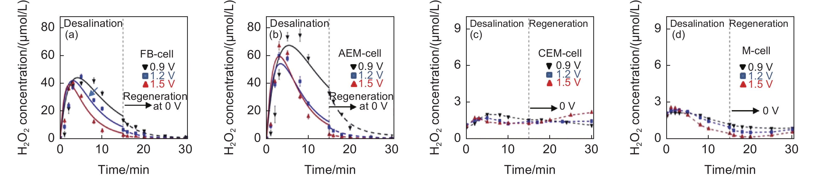
Figure 21. Changes in H2O2 concentration in the effluent during charging at different voltages (0.9, 1.2 and 1.5 V) and discharging (0 V ) in different type CDI cells: (a) symmetric FB-CDI cell, (b) AEM-CDI cell, (c) CEM-CDI cell, and (d) M-CDI-cell. Reprinted with permission from Ref.[42]. Copyright (2017) by Elsevier

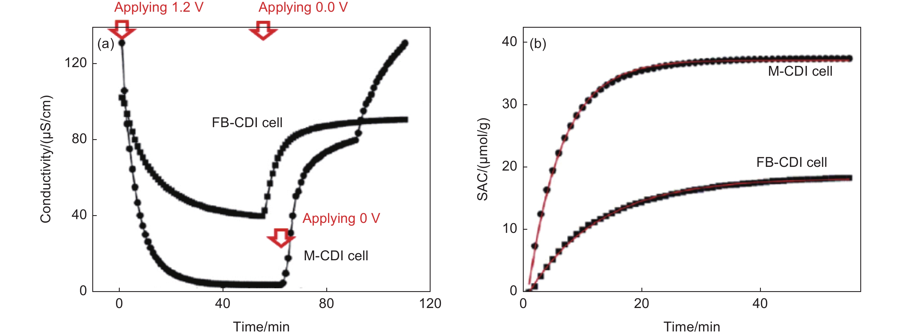
Figure 22. Performance of M-CDI cell using SWCNT electrodes in FB-CDI using the same CNT electrodes: (a) conductivity change with time and (b) change in SAC with time. Conductivity of the initial solution is around 100 μS/cm and the voltage applied is 1.2 V. Reprinted with permission from Ref.[45]. Copyright (2011) by Elsevier

Figure 23. Desalination performance of M-CDI using commercial ACC electrode with CEM and AEM: (a) desalination and regeneration profiles in comparison to FB-CDI, and (b) change in energy consumption and salt removal percentage with flow rate of salt solution and (c) those with DC voltage applied. Reprinted with permission from Ref.[47]. Copyright (2006) by Elsevier

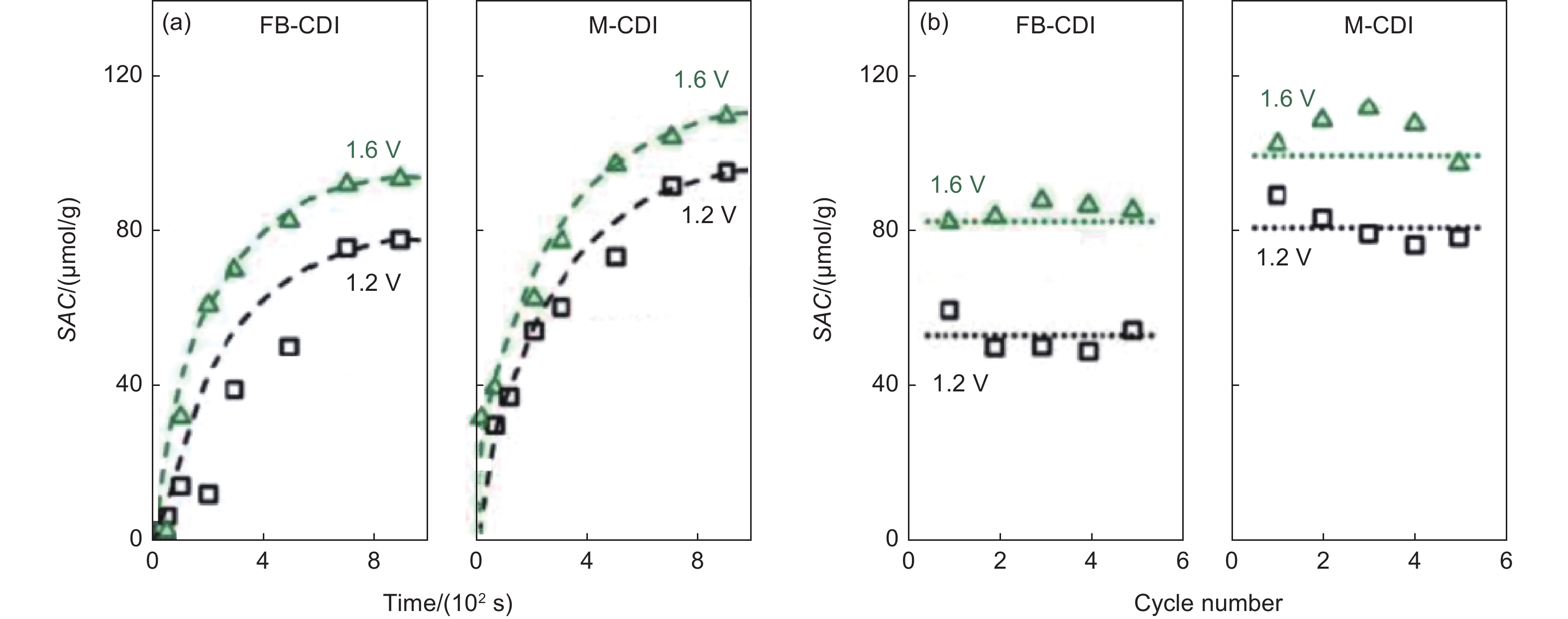
Figure 24. CDI cells using rod-electrodes with or without ion-exchange membrane (FB-CDI and M-CDI): (a) adsorption kinetics and (b) cycle performance. Experimental points shown in the figures are average values of the values obtained by 12 cells. Reprinted with permission from Ref. [48]. Copyright (2012) by American Chemical Society

Figure 25. Comparison in the CDI performances between FB-CDI cell and FTE-CDI cell using carbon electrodes of (a) a carbon nanofoam and (b) an ACC. Reprinted with permission from Ref. [52]. Copyright (2018) by Elsevier

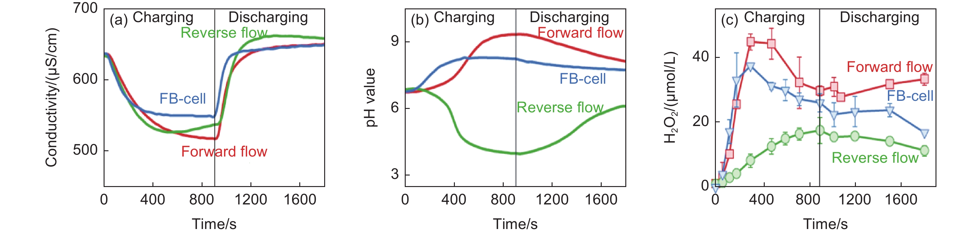
Figure 26. Change in conductivity, pH and H2O2 concentration of the effluent passed through the cells, FTE-CDI cell with a forward flow, that with a reverse flow and symmetric FB-CDI cell at an applied voltage of 1.2 V with time during charging (desalination process) and discharge (regeneration process): (a) conductivity, (b) pH and (c) H2O2 concentration. Reprinted with permission from Ref.[53]. Copyright (2019) by Elsevier

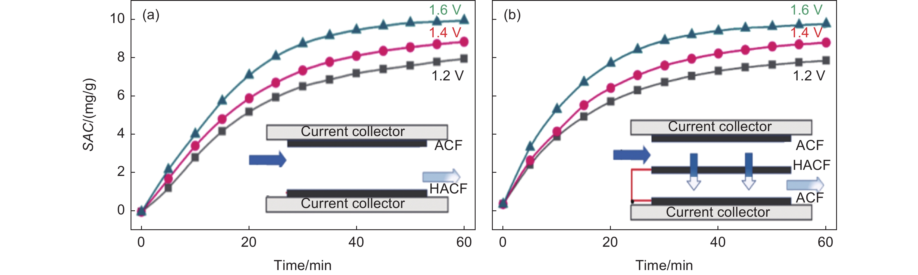
Figure 27. Salt adsorption kinetics at different voltages (1.2-1.6 V) constructed from commercial activated carbon fiber felt (ACF) and HCl-treated ACF (HACF); (a) asymmetric FB-cell and (b) 3-CDI (inserted a flow-through electrode). Reprinted with permission from Ref. [56]. Copyright (2021) by Elsevier

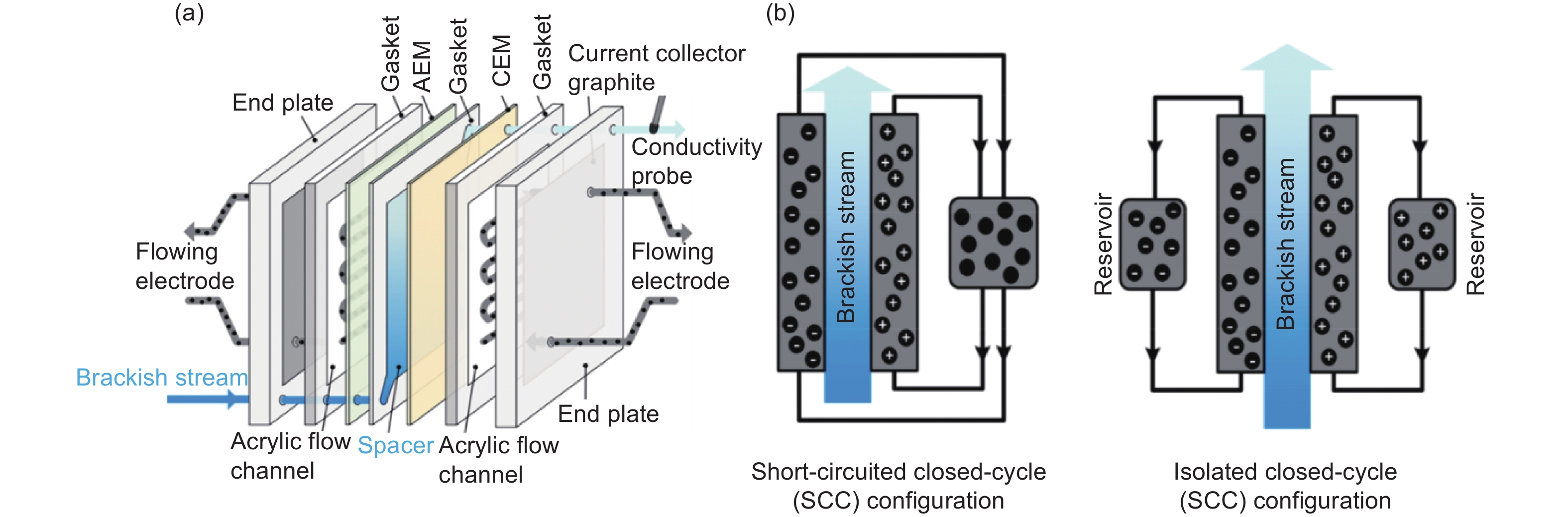
Figure 28. Schematic representations of (a) the structure of the CDI cell and (b) short-circuited closed-cycle (SCC) and isolated closed-cycle (ICC) configuration of the system. Reprinted with permission from Ref. [60]. Copyright (2018) by American Chemical Society

Figure 29. FE-CDI cell for water desalination and softening by a mixture of commercial AC and carbon black as the flowing electrode: (a) energy comparison of SCC and ICC operations, (b) relation between average salt removal rate (ASRR) and energy-normalized removed salt (ENRS) in SCC operation at different HRT (different flow rate of brackish water), (c) voltage changes with elapsed time in ICC and SCC operations. Reprinted with permission from Ref. [60]. Copyright (2018) by American Chemical Society

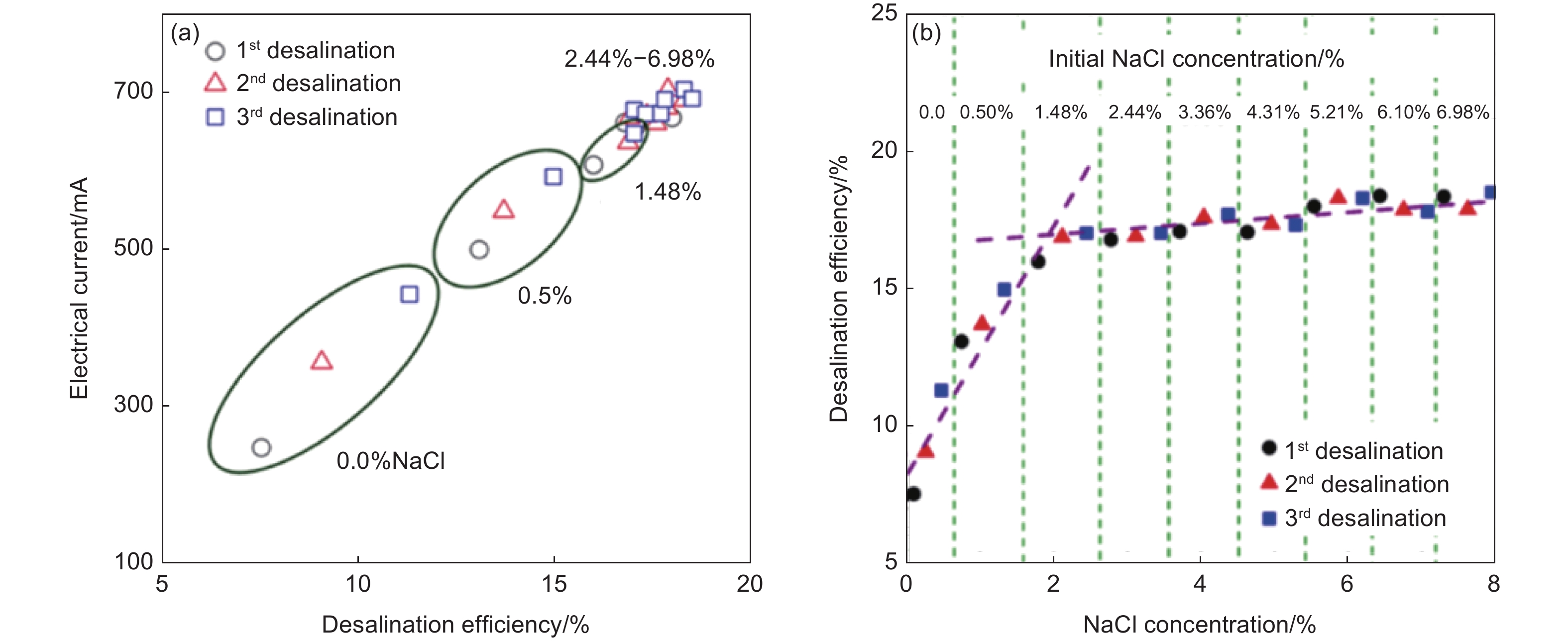
Figure 30. Desalination performances of the FE-CDI cell with SCC operation: (a) the relation between desalination efficiency and electrical current with varying NaCl concentrations (0-6.98%) and (b) the relation between desalination efficiency and NaCl concentration in the flowing-electrode after 1st/2nd/3rd desalination processes. Reprinted with permission from Ref. [62]. Copyright (2016) by American Chemical Society

Figure 31. Schematic representation of a gradient FE-CDI system in the gradient single cycle (GSC). Reprinted with permission from Ref. [66]. Copyright (2021) by American Chemical Society

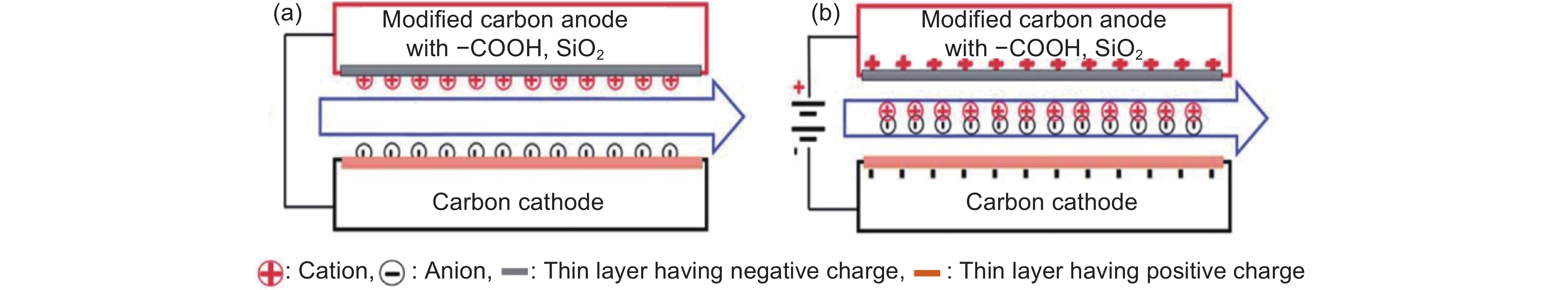
Figure 32. Schematics of the inverted-CDI cell: (a) desalination process and (b) desorption (regeneration)[68]

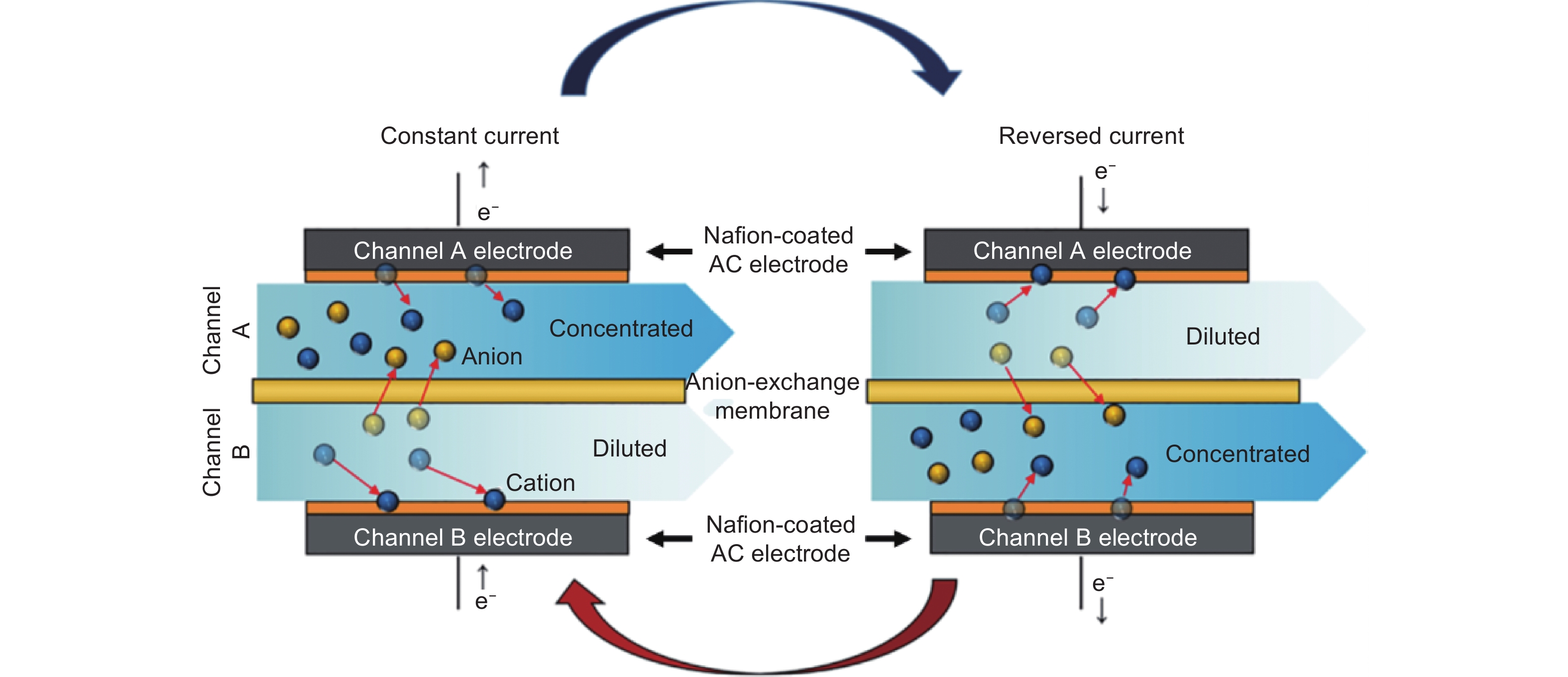
Figure 33. Schematic illustration of the rocking-chair-CDI cell. Reprinted with permission from Ref.[70]. Copyright (2018) by American Chemical Society

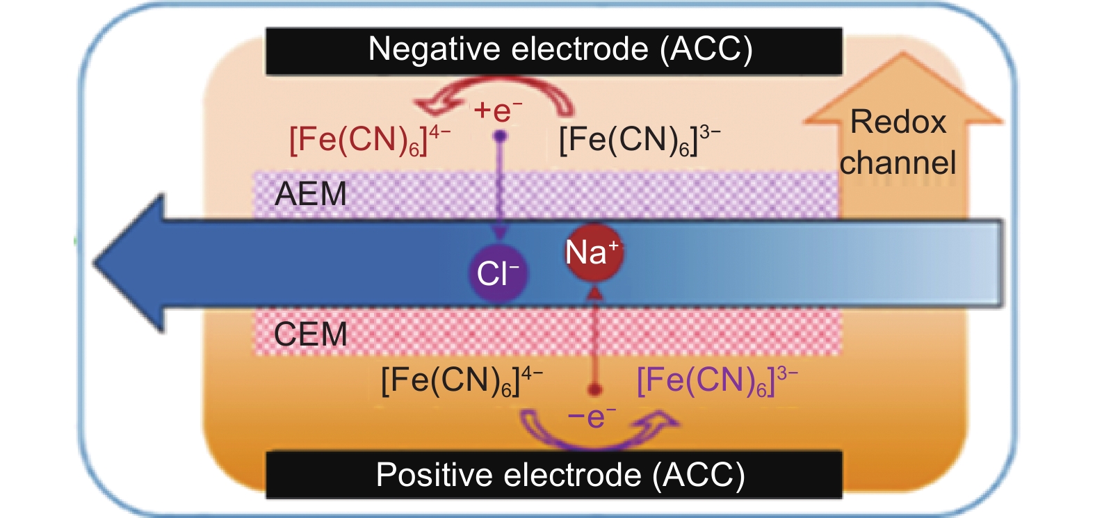
Figure 34. Schematic illustration of a redox-flow DI cell. Reprinted with permission from Ref.[73]. Copyright (2022) by Elsevier

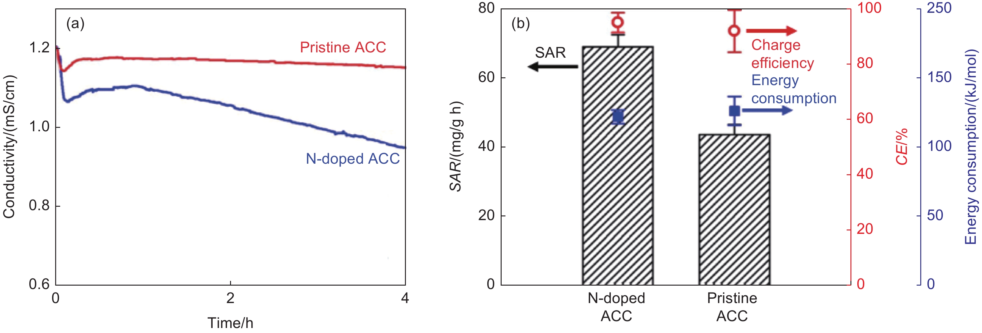
Figure 35. Performance of the redox-flow DI cell using electrodes of a commercial (pristine) ACC and N-doped ACC: (a) conductivity profiles of the effluents when the pristine and N-doped ACCs were used, and (b) the desalination performance the cells using the pristine and N-doped ACCs. Reprinted with permission from Ref. [74]. Copyright (2021) by Elsevier

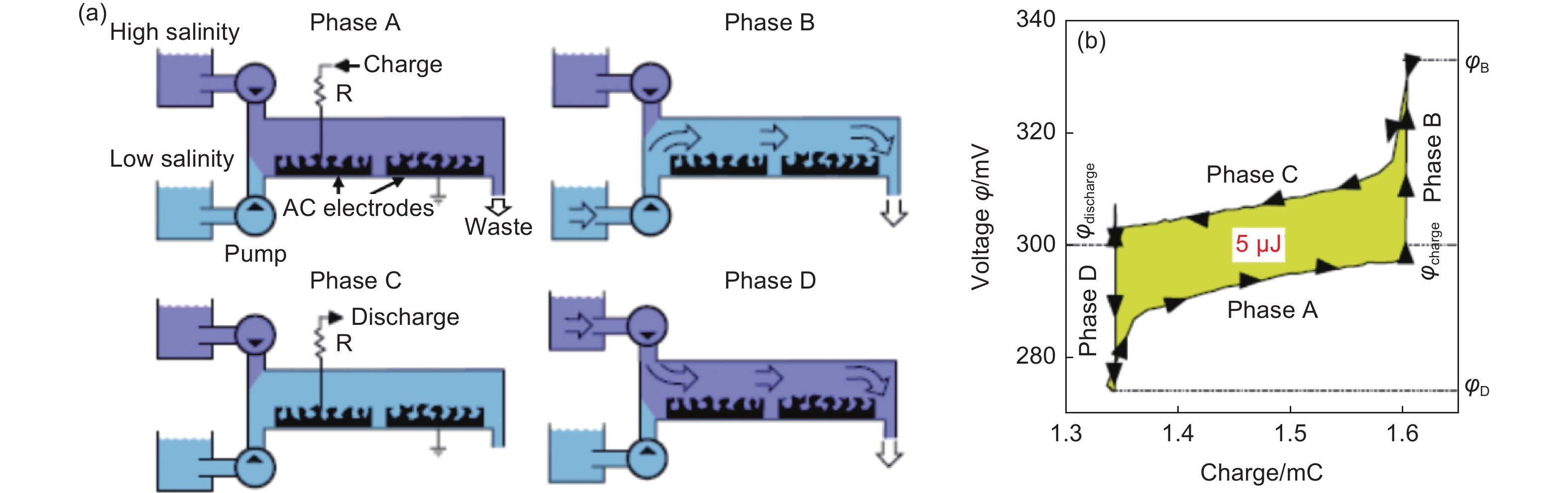
Figure 36. Cycle for extracting energy from salinity difference: (a) scheme of the four phases of the cycle and (b) the potential vs. charge relation during cycling. An extracted energy in this case is 5 μJ. Reprinted with permission from Ref. [75]. Copyright (2009) by Elsevier

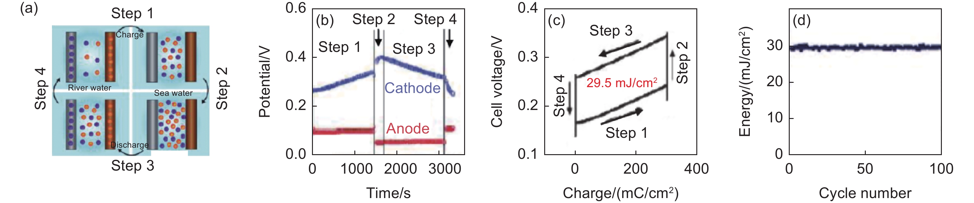
Figure 37. A “mixing entropy battery” using NaCl water with different concentrations (river water and seawater): (a) schematic illustration of the working principle of the battery, (b) change in cell potential in a cycle, (c) change the cell potential with cell charge, the defined area being equal to the extracted energy, and (d) cycle stability for energy extraction. Reprinted with permission from Ref. [76]. Copyright (2011) by Elsevier

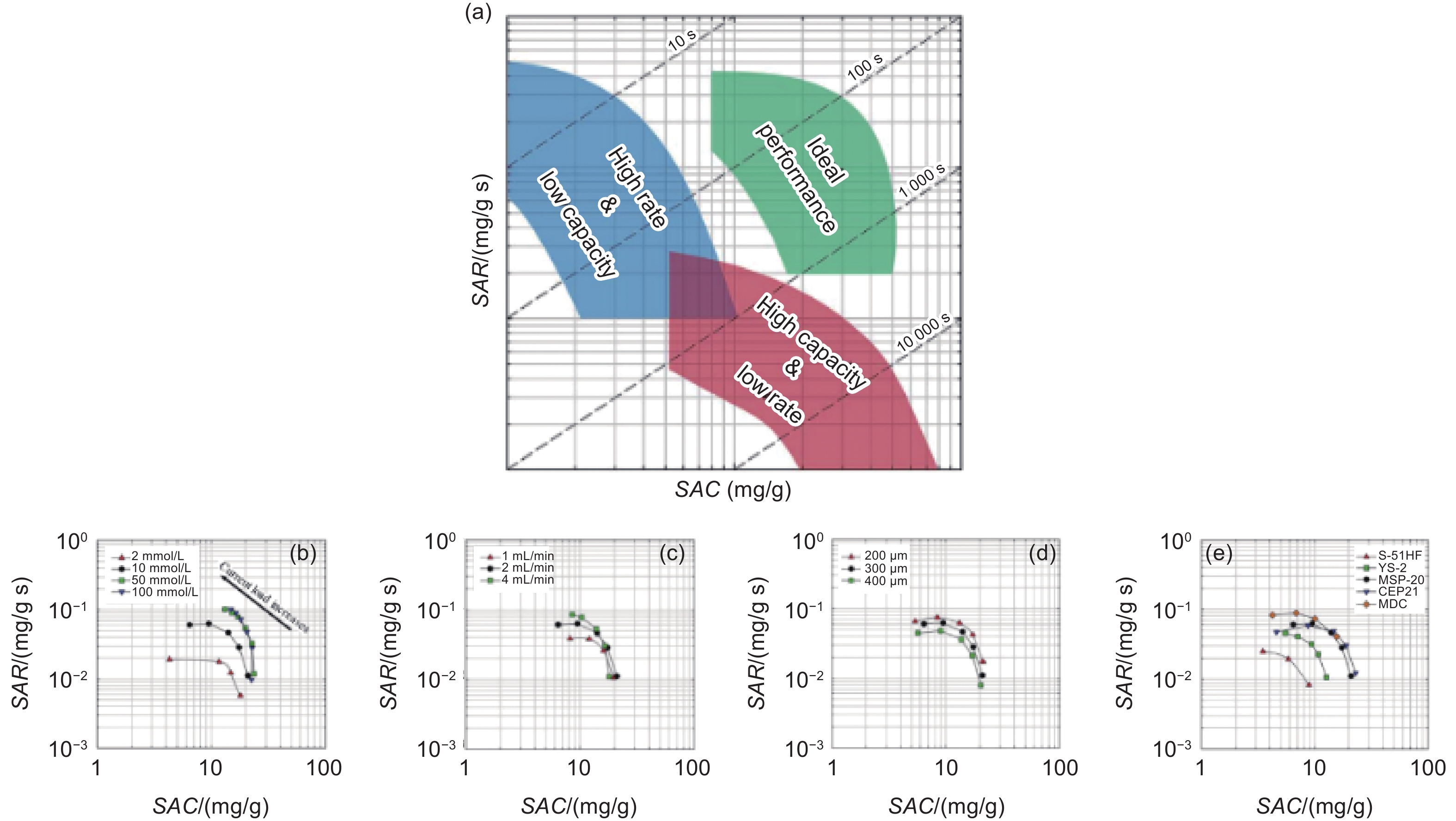
Figure 38. CDI ragone plots for CDI performance[83]: (a) A conceptual diagram of a CDI Ragone plot. Effect of various parameters on the CDI Ragone plot. Each plot shows the effect of the (b) salt concentration, (c) flow rate, (d) electrode thickness, and (e) type of carbon material
Table 1. Pore structure parameters of the porous carbons prepared from the mixtures of potassium citrate (P), urea (U) and ammonium citrate (A). Reprinted with permission from Ref. [11]. Copyright (2023) by Elsevier
Code Precursors SBET/(m2/g) Vtotal/(cm3/g) Vmicro/(cm3/g) Vmeso/(cm3/g) Vmicro/ Vtotal (%) Vmeso/ Vtotal (%) PCP P 1159 0.66 0.48 0.18 73 27 PCPA P+A (5/1) 1668 0.90 0.52 0.38 58 42 PCPU P+U (1/1) 2785 1.65 0.81 0.84 49 51 PCPUA P+U+A (5/5/1) 3200 2.49 1.05 1.44 42 58  下载: 导出CSV
Table 2. Pore structure parameters of the carbons derived from cocoon wastewater. Reprinted with permission from Ref. [13]. Copyright (2023) by Elsevier
Code ZnCl2 concentration/(mol/L) SBET/(m2/g) Vtotal/(cm3/g) Vmicro/Vtotal
(%)Vmeso/Vtotal (%) Vmacro/Vtotal
(%)CWC-0.5 0.5 1295 0.69 73.1 26.7 0.2 CWC-1.0 1.0 1311 0.74 69.5 30.3 0.2 CWC-1.5 1.5 1282 1.11 23.1 75.5 1.4 CWC-2.0 2.0 911 1.21 16.1 69.1 14.8 CWC-0.0 0.0 1409 1.14 31.0 62.7 6.3
下载: 导出CSV
Table 3. SAC and CE of the FB-CDI cells using the carbons derived from the biochar, AcB, AmB, NfB as the electrode materials. Reprinted with permission from Ref. [15]. Copyright (2021) by Elsevier
Cell configuration SAC/(mg/g) SAC/(mmol/g) CE/% Positive Negative Symmetric AcB AcB 6.01 0.103 21.42
AsymmetricNfB AcB 7.33 0.125 22.59 AcB AmB 5.31 0.090 17.01 NfB AmB 9.25 0.156 27.81
下载: 导出CSV
Table 4. Pore structure parameters and elemental compositions of the carbons derived from ZIF-8 itself, and ZIF-8 with AF and (AF+AP) (N-EPC and NP-EPC)[33]
Carbon Pore structure parameters Elemental composition/at% SBET/(m2/g) Vtotal/(cm3/g) Vmicro/(cm3/g) Vmicro/
VtotalC O N P N/P
ratioZIF-8-C 1044 0.49 0.45 0.92 78.1 6.8 15.1 N-EPC 1066 0.60 0.28 0.47 84.5 5.9 8.6 NP-EPC 1166 0.72 0.13 0.18 78.6 16.8 2.9 1.7 1.71
下载: 导出CSV
Table 5. Desalination performance (SAC, CE and energy consumption) of the CDI cells with different configuration using the polygrycerol-derived activated carbon (PGAC) as the electrode material. Reprinted with permission from Ref. [43]. Copyright (2022) by Elsevier
Electrode configuration Ion-exchange membrane Cell voltage applied/V SAC/(mg/g) CE/% Energy consumption/(J/mg)
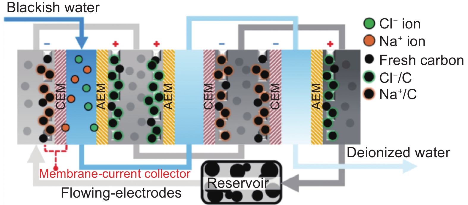
FB-cell
Symmetric1.1 10.8 65.4 2.8 1.2 14.2 62.9 3.1 1.4 13.7 51.2 4.6 Asymmetric * 1.2 11.5 88.4 2.2 M-CDI AEM and CEM 1.2 17.6 97.9 2.0 1.4 23.4 102.9 2.3 1.6 27.1 102.2 2.6 CEM 1.2 16.8 98.9 2.0 1.4 10.8 81.6 2.8 Note: *PGAC at the positive electrode and HNO3-treated PGAC at the negative electrodes.
下载: 导出CSV
Table 6. Commercial carbon nanofoam (NF), activated carbon cloth (ACC) and another ACC (K-ACC) used for construction of symmetric FB- CDI-cell and FTE-CDI-cells. Reprinted with permission from Ref. [52]. Copyright (2018) by Elsevier
Carbon Thickness/μm SBET/(m2/g) Vmicro/(cm3/g) Capacitance/(F/g) Resistance/(Ω/sq) O-content/at% SEM features NF 210 705 0.27 100 0.4 2.1 10-100 cracks, <10 nm pores ACC 500 2980 0.44 110 3.9 6.6 13 μm-diameter fibers, <300 nm pores K-ACC 800 1913 0.31 80 3.3 4.8 14 μm-diameter fibers, <300 nm pores
下载: 导出CSV
Table 7. Comparison in salt removal efficiency, current, and power consumption for three CDI cells. Reprinted with permission from Ref.[69]. Copyright (2011) by Elsevier
Cells Applied potential/V Solution conductivity/(μS/cm) Salt removal efficiency/% Current after 30 min/mA Power consumption/(mW/h) Initial After 30 min FB-CDI cell 1.8 190.8 39.9 79.1 235.7 212.3 M-CDI cell 1.8 185.1 168.0 9.2 2.6 2.3 Inverted-CDI cell 1.8 188.9 31.5 83.4 25.6 23.1
下载: 导出CSV
-
[1] Gao M, Zhu L, Peh C K, et al. Solar absorber material and system designs for photothermal water vaporization towards clean water and energy production[J]. Energy & Environmental Science,2019,12(3):841-864. [2] Huang Z H, Yang Z, Kang F, et al. Carbon electrodes for capacitive deionization[J]. Journal of Materials Chemistry A,2017,5(2):470-496. doi: 10.1039/C6TA06733F [3] Zhang C, He D, Ma J, et al. Faradaic reactions in capacitive deionization (CDI)-problems and possibilities: A review[J]. Water Research,2018,128:314-330. doi: 10.1016/j.watres.2017.10.024 [4] Tang W, Liang J, He D, et al. Various cell architectures of capacitive deionization: Recent advances and future trends[J]. Water Research,2019,150:225-251. doi: 10.1016/j.watres.2018.11.064 [5] Anis S F, Hashaikeh R, Hilal N. Functional materials in desalination: A review[J]. Desalination,2019,468:114077. [6] Kim N, Lee J, Kim S, et al. Short review of multichannel membrane capacitive deionization: principle, current status, and future prospect[J]. Applied Sciences,2020,10(2):683. doi: 10.3390/app10020683 [7] Vafakhah S, Beiramzadeh Z, Saeedikhani M, et al. A review on free-standing electrodes for energy-effective desalination: Recent advances and perspectives in capacitive deionization[J]. Desalination,2020,493:114662. doi: 10.1016/j.desal.2020.114662 [8] Xing W, Liang J, Tang W, et al. Versatile applications of capacitive deionization (CDI)-based technologies[J]. Desalination,2020,482:114390. doi: 10.1016/j.desal.2020.114390 [9] Oladunni J, Zain J H, Hai A, et al. A comprehensive review on recently developed carbon based nanocomposites for capacitive deionization: From theory to practice[J]. Separation and Purification Technology,2018,207:291-320. doi: 10.1016/j.seppur.2018.06.046 [10] Nakayama Y, Imamura E, Noda S. Capacitive deionization characteristics of compressed granular activated carbon[J]. Separation and Purification Technology,2021,277:119454. [11] Qiang H, Shi M, Wang F, et al. Green synthesis of high N-doped hierarchical porous carbon nanogranules with ultra-high specific surface area and porosity for capacitive deionization[J]. Separation and Purification Technology,2023,308:122918. doi: 10.1016/j.seppur.2022.122918 [12] Liu M, Xu M, Xue Y, et al. efficient capacitive deionization using natural basswood-derived, freestanding, hierarchically porous carbon electrodes[J]. ACS Applied Materials & Interfaces,2018,10(37):31260-31270. [13] Zheng S M, Yuan Z H, Dionysiou D D, et al. Silkworm cocoon waste-derived nitrogen-doped hierarchical porous carbon as robust electrode materials for efficient capacitive desalination[J]. Chemical Engineering Journal,2023,458:141471. doi: 10.1016/j.cej.2023.141471 [14] Zhao C, Wang Q, Chang S, et al. Efficient transport system of cultivated mushroom mycelium enables its derived carbon with high performance electrochemical desalination capability[J]. Carbon,2022,196:699-707. doi: 10.1016/j.carbon.2022.05.020 [15] Stephanie H, Mlsna T E, Wipf D O. Functionalized biochar electrodes for asymmetrical capacitive deionization[J]. Desalination,2021,516:115240. [16] Song X, Fang D, Huo S, et al. 3D-ordered honeycomb-like nitrogen-doped micro–mesoporous carbon for brackish water desalination using capacitive deionization[J]. Environmental Science: Nano,2021,8(8):2191-2203. doi: 10.1039/D1EN00276G [17] Guo J, Xu X, Hill J P, et al. Graphene–carbon 2D heterostructures with hierarchically-porous P, N-doped layered architecture for capacitive deionization[J]. Chemical Science,2021,12(30):10334-10340. doi: 10.1039/D1SC00915J [18] Halabaso E R, Salvacion J W L, Kuncoro E P, et al. Highly efficient capacitive deionization of brackish water with manganese vanadate nanorod decorated reduced graphene oxide electrode[J]. Environmental Science:Nano,2021,8(10):2844-2854. doi: 10.1039/D1EN00514F [19] Song X, Fang D, Huo S, et al. Exceptional capacitive deionization desalination performance of hollow bowl-like carbon derived from MOFs in brackish water[J]. Separation and Purification Technology,2021,278:119550. doi: 10.1016/j.seppur.2021.119550 [20] Kyaw H H, Myint M T Z, Al-Harthi S, et al. Electric field enhanced in situ silica nanoparticles grafted activated carbon cloth electrodes for capacitive deionization[J]. Separation and Purification Technology,2022,281:119888. doi: 10.1016/j.seppur.2021.119888 [21] Zong M, Huo S, Liu Y, et al. Hydrangea-like nitrogen-doped porous carbons derived from NH2-MIL-53(Al) for high-performance capacitive deionization[J]. Separation and Purification Technology,2021,256:117818. doi: 10.1016/j.seppur.2020.117818 [22] Hu B, Shang X, Nie P, et al. Lithium ion sieve modified three-dimensional graphene electrode for selective extraction of lithium by capacitive deionization[J]. Journal of Colloid and Interface Science,2022,612:392-400. doi: 10.1016/j.jcis.2021.12.181 [23] Bai Y, Huang Z H, Yu X L, et al. Graphene oxide-embedded porous carbon nanofiber webs by electrospinning for capacitive deionization[J]. Colloids and Surfaces A:Physicochemical and Engineering Aspects,2014,444:153-158. [24] Wang G, Dong Q, Wu T, et al. Ultrasound-assisted preparation of electrospun carbon fiber/graphene electrodes for capacitive deionization: Importance and unique role of electrical conductivity[J]. Carbon,2016,103:311-317. doi: 10.1016/j.carbon.2016.03.025 [25] Liu Y, Du X, Wang Z, et al. Layered double hydroxide coated electrospun carbon nanofibers as the chloride capturing electrode for ultrafast electrochemical deionization[J]. Journal of Colloid and Interface Science,2022,609:289-296. doi: 10.1016/j.jcis.2021.12.001 [26] Chen C, Men L, Liu A, et al. Enhanced electrochemical and capacitive deionization performances of single-layer graphene oxide/nitrogen-doped porous carbon/activated carbon fiber composite electrodes[J]. Journal of Environmental Chemical Engineering,2022,10(6):108696. doi: 10.1016/j.jece.2022.108696 [27] Nie P, Wang S, Shang X, et al. Self-supporting porous carbon nanofibers with opposite surface charges for high-performance inverted capacitive deionization[J]. Desalination,2021,520:115340. doi: 10.1016/j.desal.2021.115340 [28] Hameed R M A, Zouli N, Abutaleb A, et al. Improving water desalination performance of electrospun carbon nanofibers by supporting with binary metallic carbide nanoparticles[J]. Ceramics International,2022,48(4):4741-4753. doi: 10.1016/j.ceramint.2021.11.010 [29] Wang P, Ma W, Xue S, et al. N-doped carbon nanosheets assembled microspheres for more effective capacitive deionization[J]. Separation and Purification Technology,2021,276:119336. doi: 10.1016/j.seppur.2021.119336 [30] Gong X, Luo W, Guo N, et al. Carbon nanofiber@ZIF-8 derived carbon nanosheet composites with a core–shell structure boosting capacitive deionization performance[J]. Journal of Materials Chemistry A,2021,9(34):18604-18613. doi: 10.1039/D1TA03804D [31] Talebi M, Ahadian M M, Shahrokhian S. Binder-free 3D graphene nanostructures on Ni foam substrate for application in capacitive deionization[J]. Diamond and Related Materials,2021,120:108612. [32] Zhang G, Li W, Chen Z, et al. Freestanding N-doped graphene membrane electrode with interconnected porous architecture for efficient capacitive deionization[J]. Carbon,2022,187:86-96. doi: 10.1016/j.carbon.2021.10.081 [33] Zhang H, Wang C, Zhang W, et al. Nitrogen, phosphorus co-doped eave-like hierarchical porous carbon for efficient capacitive deionization[J]. Journal of Materials Chemistry A,2021,9(21):12807-12817. doi: 10.1039/D0TA10797B [34] Lee J H, Bae W S, Choi J H. Electrode reactions and adsorption/desorption performance related to the applied potential in a capacitive deionization process[J]. Desalination,2010,258(1):159-163. [35] Choi J-H. Determination of the electrode potential causing Faradaic reactions in membrane capacitive deionization[J]. Desalination,2014,347:224-229. [36] Bouhadana Y, Avraham E, Noked M, et al. Capacitive deionization of NaCl solutions at non-steady-state conditions: Inversion functionality of the carbon electrodes[J]. The Journal of Physical Chemistry C,2011,115(33):16567-16573. doi: 10.1021/jp2047486 [37] Cohen I, Avraham E, Bouhadana Y, et al. Long term stability of capacitive de-ionization processes for water desalination: The challenge of positive electrodes corrosion[J]. Electrochimica Acta,2013,106:91-100. doi: 10.1016/j.electacta.2013.05.029 [38] He D, Wong C E, Tang W, et al. Faradaic reactions in water desalination by batch-mode capacitive deionization[J]. Environmental Science & Technology Letters,2016,3(5):222-226. [39] Taha M M, Anwar S E, Ramadan M, et al. Controlled fabrication of mesoporous electrodes with unprecedented stability for water capacitive deionization under harsh conditions in large size cells[J]. Desalination,2021,511:115099. doi: 10.1016/j.desal.2021.115099 [40] Adorna J, Borines M, Dang V D, et al. Coconut shell derived activated biochar–manganese dioxide nanocomposites for high performance capacitive deionization[J]. Desalination,2020,492:114602. doi: 10.1016/j.desal.2020.114602 [41] Wang H, Edaño L, Valentino L, et al. Capacitive deionization using carbon derived from an array of zeolitic-imidazolate frameworks[J]. Nano Energy,2020,77:105304. doi: 10.1016/j.nanoen.2020.105304 [42] Tang W, He D, Zhang C, et al. Comparison of Faradaic reactions in capacitive deionization (CDI) and membrane capacitive deionization (MCDI) water treatment processes[J]. Water Research,2017,120:229-237. doi: 10.1016/j.watres.2017.05.009 [43] Juchen P T, Barcelos K M, Oliveira K S G C, et al. Using crude residual glycerol as precursor of sustainable activated carbon electrodes for capacitive deionization desalination[J]. Chemical Engineering Journal,2022,429:132209. doi: 10.1016/j.cej.2021.132209 [44] Son J W, Choi J H. Suppression of electrode reactions and enhancement of the desalination performance of capacitive deionization using a composite carbon electrode coated with an ion-exchange polymer[J]. Separation and Purification Technology,2021,278:119503. [45] Li H, Zou L. Ion-exchange membrane capacitive deionization: A new strategy for brackish water desalination[J]. Desalination,2011,275(1):62-66. [46] Biesheuvel P M, van der Wal A. Membrane capacitive deionization[J]. Journal of Membrane Science,2010,346(2):256-262. [47] Lee J B, Park K K, Eum H M, et al. Desalination of a thermal power plant wastewater by membrane capacitive deionization[J]. Desalination,2006,196(1):125-134. [48] Porada S, Sales B B, Hamelers H V M, et al. Water desalination with wires[J]. The Journal of Physical Chemistry Letters,2012,3(12):1613-1618. doi: 10.1021/jz3005514 [49] Suss M E, Baumann T F, Bourcier W L, et al. Capacitive desalination with flow-through electrodes[J]. Energy & Environmental Science,2012,5(11):9511-9519. [50] Baumann T F, Worsley M A, Han T Y J, et al. High surface area carbon aerogel monoliths with hierarchical porosity[J]. Journal of Non-Crystalline Solids,2008,354(29):3513-3515. doi: 10.1016/j.jnoncrysol.2008.03.006 [51] Wang G, Qian B, Wang Y, et al. Electrospun porous hierarchical carbon nanofibers with tailored structures for supercapacitors and capacitive deionization[J]. New Journal of Chemistry,2016,40(4):3786-3792. doi: 10.1039/C5NJ02963E [52] Remillard E M, Shocron A N, Rahill J, et al. A direct comparison of flow-by and flow-through capacitive deionization[J]. Desalination,2018,444:169-177. doi: 10.1016/j.desal.2018.01.018 [53] Zhang C, He D, Ma J, et al. Comparison of faradaic reactions in flow-through and flow-by capacitive deionization (CDI) systems[J]. Electrochimica Acta,2019,299:727-735. doi: 10.1016/j.electacta.2019.01.058 [54] Zhang X, Dutta J. X-Fe (X = Mn, Co, Cu) Prussian blue analogue-modified carbon cloth electrodes for capacitive deionization[J]. ACS Applied Energy Materials,2021,4(8):8275-8284. [55] Reale E R, Regenwetter L, Agrawal A, et al. Low porosity, high areal-capacity prussian blue analogue electrodes enhance salt removal and thermodynamic efficiency in symmetric Faradaic deionization with automated fluid control[J]. Water Research X,2021,13:100116. doi: 10.1016/j.wroa.2021.100116 [56] Shi M, Qiang H, Chen C, et al. Construction and evaluation of a novel three-electrode capacitive deionization system with high desalination performance[J]. Separation and Purification Technology,2021,273:118976. doi: 10.1016/j.seppur.2021.118976 [57] Laxman K, Myint M T Z, Al Abri M, et al. Desalination and disinfection of inland brackish ground water in a capacitive deionization cell using nanoporous activated carbon cloth electrodes[J]. Desalination,2015,362:126-132. doi: 10.1016/j.desal.2015.02.010 [58] Jeon S I, Park H R, Yeo J G, et al. Desalination via a new membrane capacitive deionization process utilizing flow-electrodes[J]. Energy & Environmental Science,2013,6(5):1471-1475. [59] Jeon S i, Yeo J g, Yang S, et al. Ion storage and energy recovery of a flow-electrode capacitive deionization process[J]. Journal of Materials Chemistry A,2014,2(18):6378-6383. doi: 10.1039/c4ta00377b [60] He C, Ma J, Zhang C, et al. Short-circuited closed-cycle operation of flow-electrode CDI for brackish water softening[J]. Environmental Science & Technology,2018,52(16):9350-9360. [61] Ma J, Ma J, Zhang C, et al. Water recovery rate in short-circuited closed-cycle operation of flow-electrode capacitive deionization (FCDI)[J]. Environmental Science & Technology,2019,53(23):13859-13867. [62] Yang S, Choi J, Yeo J G, et al. Flow-electrode capacitive deionization using an aqueous electrolyte with a high salt concentration[J]. Environmental Science & Technology,2016,50(11):5892-5899. [63] Yang S, Kim H, Jeon S I, et al. Analysis of the desalting performance of flow-electrode capacitive deionization under short-circuited closed cycle operation[J]. Desalination,2017,424:110-121. doi: 10.1016/j.desal.2017.09.032 [64] Ma J, Liang P, Sun X, et al. Energy recovery from the flow-electrode capacitive deionization[J]. Journal of Power Sources,2019,421:50-55. doi: 10.1016/j.jpowsour.2019.02.082 [65] Doornbusch G J, Dykstra J E, Biesheuvel P M, et al. Fluidized bed electrodes with high carbon loading for water desalination by capacitive deionization[J]. Journal of Materials Chemistry A,2016,4(10):3642-3647. doi: 10.1039/C5TA10316A [66] Xu L, Mao Y, Zong Y, et al. Membrane-current collector-based flow-electrode capacitive deionization system: A novel stack configuration for scale-up desalination[J]. Environmental Science & Technology,2021,55(19):13286-13296. [67] Xu L, Ding R, Mao Y, et al. Selective recovery of phosphorus and urea from fresh human urine using a liquid membrane chamber integrated flow-electrode electrochemical system[J]. Water Research,2021,202:117423. doi: 10.1016/j.watres.2021.117423 [68] Gao X, Omosebi A, Landon J, et al. Surface charge enhanced carbon electrodes for stable and efficient capacitive deionization using inverted adsorption–desorption behavior[J]. Energy & Environmental Science,2015,8(3):897-909. [69] Lee J Y, Seo S J, Yun S H, et al. Preparation of ion exchanger layered electrodes for advanced membrane capacitive deionization (MCDI)[J]. Water Research,2011,45(17):5375-5380. doi: 10.1016/j.watres.2011.06.028 [70] Lee J, Jo K, Lee J, et al. Rocking-chair capacitive deionization for continuous brackish water desalination[J]. ACS Sustainable Chemistry & Engineering,2018,6(8):10815-10822. [71] Lee J, Kim S, Kim C, et al. Hybrid capacitive deionization to enhance the desalination performance of capacitive techniques[J]. Energy & Environmental Science,2014,7(11):3683-3689. [72] Smith K C, Dmello R. Na-ion desalination (NID) enabled by Na-blocking membranes and symmetric na-intercalation: Porous-electrode modeling[J]. Journal of the Electrochemical Society,2016,163(3):A530. [73] Kim N, Jeon J, Elbert J, et al. Redox-mediated electrochemical desalination for waste valorization in dairy production[J]. Chemical Engineering Journal,2022,428:131082. doi: 10.1016/j.cej.2021.131082 [74] Ahn D, Kim D, Park J H, et al. Enhanced desalination performance of nitrogen-doped porous carbon electrode in redox-mediated deionization[J]. Desalination,2021,520:115333. doi: 10.1016/j.desal.2021.115333 [75] Brogioli D. Extracting renewable energy from a salinity difference using a capacitor[J]. Physical Review Letters,2009,103(5):058501. [76] La Mantia F, Pasta M, Deshazer H D, et al. Batteries for efficient energy extraction from a water salinity difference[J]. Nano Letters,2011,11(4):1810-1813. doi: 10.1021/nl200500s [77] Pasta M, Wessells C D, Cui Y, et al. A desalination battery[J]. Nano Letters,2012,12(2):839-843. doi: 10.1021/nl203889e [78] Pasta M, Battistel A, La Mantia F. Batteries for lithium recovery from brines[J]. Energy & Environmental Science,2012,5(11):9487-9491. [79] Lee J, Yu S-H, Kim C, et al. Highly selective lithium recovery from brine using a λ-MnO2–Ag battery[J]. Physical Chemistry Chemical Physics,2013,15(20):7690-7695. doi: 10.1039/c3cp50919b [80] Kim T, Rahimi M, Logan B E, et al. Harvesting energy from salinity differences using battery electrodes in a concentration flow cell[J]. Environmental Science & Technology,2016,50(17):9791-9797. [81] Kim T, Gorski C A, Logan B E. Low energy desalination using battery electrode deionization[J]. Environmental Science & Technology Letters,2017,4(10):444-449. [82] Sales B B, Saakes M, Post J W, et al. Direct power production from a water salinity difference in a membrane-modified supercapacitor flow cell[J]. Environmental Science & Technology,2010,44(14):5661-5665. [83] Kim T, Yoon J. CDI ragone plot as a functional tool to evaluate desalination performance in capacitive deionization[J]. RSC Advances,2015,5(2):1456-1461. -


 点击查看大图

计量
- 文章访问数: 806
- HTML全文浏览量: 229
- PDF下载量: 171
- 被引次数: 0